
PXE + EPX. PERFECT TOGETHER
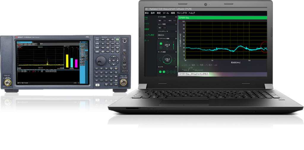
THE LATEST IN EMI SOLUTIONS
Have you experienced these issues when performing EMI measurements?
- Measurements vary and lack reproducibility
- Measured values differ even when using the same EUT
- During mitigation, you cannot find bad signals, making it difficult to know if improvements have been effective.
- The EMI receiver is difficult to operate, preventing effective noise observation
With an FFT-based EMI receiver, all of these problems can be solved! So, what exactly are FFT-based measurement and FFT-based solutions?

Let us introduce you to the new EMI compliance measurement solutions, provided by TOYO Corporation and Keysight Technologies, which make use of FFT-based measurements. From the principles underlying the new solutions to examples of effective measurement and details about our products, this document provides information that is both relevant and useful for those working in the field of EMI measurements.
TOYO also offers “EMINT”, a new and unique EMI mitigation software that employs AI (Artificial Intelligence) to accelerate mitigation efforts and reduce mean time to problem resolution.
Frequently Asked Questions
- What are FFT-based measurements?
- Examples of effective measurements using A-TDS
- A-TDS-compatible products
- Additional Frequently Asked Questions
1. What are FFT-based measurements?
FFT (Fast Fourier Transformation), used in measurement, takes a signal sampled in the time domain as is done on an oscilloscope, and, via data processing, converts and displays it in the frequency domain (frequency spectrum).
Conventionally, frequency spectrum analysis such as EMC primarily involved sweep measurement performed using the super heterodyne method. This was because FFT had a number of limitations, described below, making it unsuitable for noise measurement, and it did not meet the measurement equipment specifications required by CISPR standards.
What were the limitations of FFT in the past?
When FFT operations are carried out, a portion of the data sampled in the time domain is discretely extracted and converted into spectrum data. This results in a significant amount of data in the time domain being lost. With CW signals, this does not cause many practical concerns, but in noise measurement, time-varying noise is missed, which harms the reliability of the values of the levels measured.
Time-Domain Scan (TDS)
FFT’s former limitations were solved by a method called Time Domain Scan (TDS). Although it uses FFT and performs the same conversion of data sampled in the time domain to frequency spectrum data, data loss is eliminated, and it meets the measurement equipment specifications required by CISPR standards, such those related to the accuracy of measured levels by applying temporal overlaps to the sampling data in FFT processing.
Missing from conventional sweep measurements, TDS has the unique ability to change data in a certain bandwidth into spectrum data at one time. As a result, even for things involving long time constants, such as QP detection, you do not need to spend the same duration as the time constant for processing the data at each measurement point, as is the case for sweep measurements. In other words, data in a specific bandwidth (30 MHz) can be processed in about the same amount of time as one measured point.
For example, for a measurement range of 150 KHz-30 MHz (RBW: 9 KHz, dwell time: 1 second)
- Using sweep measurement, QP measurements take a little under 4 hours
- With TDS, under the same conditions, it takes 2 seconds
Therefore, under particular measurement conditions, the amount of time spent on measurements could be greatly reduced. However, because of the limitations of TDS, which will be described next, there were many cases in which users could not reap its benefits.
What are the limitations of TDS?
Missing from conventional sweep measurement, TDS’s unique feature is the ability to change data in a certain bandwidth into spectrum data at one time. As a result, even for things involving long time constants, such as QP detection, you do not need to spend the same duration as the time constant for processing the data at each measurement point, as is the case for sweep measurements. In other words, data in a specific bandwidth (30 MHz) can be processed in about the same amount of time as one measured point.
The four types of measurement equipment listed in CISPR 16-1-1 are the following:
- Tunable voltmeter
- EMI receiver
- Spectrum analyzer
- FFT-based measuring instrument
It goes without saying that an FFT-based measuring instrument, like the other measurement instruments, must meet the specifications prescribed by CISPR standards. However, conventional FFT cannot be used as-is for EMI compliance measurement because of the requirement that a signal be continuously evaluated during measurements.
TDS is one method that can allow FFT to be used while meeting the requirements mentioned above.
Accelerated Time Domain Scan (A-TDS)
TDS brought advantages for a portion of EMI measurement, such as QP measurement in the conducted emission band, but it was A-TDS, with its further increase in functionality, that aimed to apply its advancements to radiated emission measurement in the 30 MHz-1 GHz range.
Using a high-performance hardware engine, A-TDS instantly expands the TDS bandwidth to 350 MHz (simultaneously with three types of detection—peak, QP, and EMI average), which is 10 times as that of the conventional TDS. Moreover, with a minimum dwell time of 50 msec and absolutely nothing missing in the time domain, signals and noise within this entire 350 MHz TDS bandwidth can be continuously measured.
This continuous gapless measurement function is called Real Time Scan (RTSC).
The RTSC has been further enhanced, making the TDS bandwidth 1 GHz from 350 MHz while maintaining the continuous gapless measurement with three types of detection across this entire 1 GHz band with a minimum dwell time of 30msec. This 1 GHz TDS band can be configured for up to 3.2GHz.
The expanded 1 GHz bandwidth not only significantly reduces the time for QP measurements up to 1 GHz, such as that used for automobiles, but with Real Time Scan, there are also major benefits for general EMI measurements in the 30 MHz-1 GHz range.
Example (automobiles): Using a measurement range of 30 MHz-1 GHz (dwell time: 1 sec, 3 types of detection: peak/QP/EMI average)
- TDS measurement time (30 MHz FFT bandwidth, RBW: 120 KHz,): about 80 sec
- A-TDS measurement time (350 MHz FFT bandwidth, RBW: 120 KHz,): about 5.8 sec
- New A-TDS measurement time (1 GHz FFT bandwidth, RBW: 9 KHz and 120 KHz,): about 2 sec
New EMI measurements enabled by Real Time Scan (RTSC)
RTSC uses TDS at its base and is capable of continuous gapless measurement of signal and noise in a 350 MHz band.
Because the peak, QP, and EMI average traces are displayed simultaneously during measurement, and RTSC is capable of dwell times as low as 50 msec, for each type of detection, one can determine when noise occurs and what it is caused by and observe the true behavior of noise fluctuations. Because RTSC operation is simple and involves only setting the start frequency, stop frequency, and dwell time, even users without a lot of experience operating spectrum analyzers can easily start using it.
New radiated emissions measurements using Real Time Scan (RTSC)
With the application of RTSC to radiated emissions measurement in the 30 MHz-1 GHz range, the following problems, mentioned above, can be solved.
Measurements vary and lack reproducibility
Measured values differ even when using the same EUT
During mitigation, you cannot find signals that exceed the limit, or it is difficult to know if improvements have been effective
The EMI receiver is difficult to operate, preventing effective noise observation
Fundamentally, RTSC does not miss any noise or any changes in fluctuating noise. Therefore, it eliminates the problem, associated with conventional sweep spectrum analyzers and EMI receivers, of variation in values depending on the measurement conditions or the test engineer taking measurements.
Moreover, those who are not experienced in the field of measurement, such as R&D engineers whose primary focus is noise mitigation, can also easily use it to observe noise behavior, allowing them to concentrate on original purposes such as mitigation and checking phenomena.
Using Real Time Scan (RTSC) for compliance testing of radiated emissions
For pre-scanning using RTSC’s gapless measurement feature, a measurement in a 30 MHz to 1000 MHz can be done with only one step. Gapless measurement reduces loss and variation compared to conventional sweep measurement, allowing for substantially more reliable measurement in a very short time.
In addition, just by picking up some typical noise from the pre-scan results and performing final measurements using full-compliance TDS, the results can be used as full-compliance measurement results.
Notes on Accelerated Time Domain Scan (A-TDS)
A-TDS has a variety of advantages, but there are some tradeoffs from widening the measurement bandwidth to 1 GHz. In the following ways, the PXE does not meet the specifications for measurement devices required by CISPR standards.
“An impulse with an extremely narrow pulse width and an RPF (repetition frequency) of 10 Hz or below may not satisfy the measurement accuracy defined by CISPR16-1-1.”
However, TOYO’s EMI measurement software “EPX” automatically determines whether such an impulse exists and if there is no such impulse, the results can be considered as fully compliant.
The noise source can be identified more easily by understanding the true behavior of noise in gapless measurements using 1 GHz RTSC and also variations can substantially be reduced regardless of the experience or knowledge of test engineers, compared to the traditional sweep measurements and narrow-band time-domain scan measurements. This will help avoid retest, rework and other unnecessary tasks.
2. Examples of effective measurements with A-TDS
Radiated emissions measurements performed using A-TDS can solve many measurement difficulties that have remained troublesome up to now. Here, we will introduce some examples of these improvements.
Example 1: “Rationally narrowing down target noise for final testing and reducing testing time”
Conventionally, when pre-scanning with a sweep spectrum analyzer or EMI receiver, QP/EMI average detection sweeps were time-consuming and could not be selected. In that situation, users had to surmise the QP/EMI average levels from peak values or its Max Hold trace, and the noise which should be measured in final testing is picked up. Then, if one takes into account the margin of the limit, a greater number of candidates will have to be measured than the noise that should actually be measured. This work is extremely time-consuming and labor-intensive. Moreover, shortcuts would result in missing the worst values that originally should have been measured.
In contrast, when using RTSC, peak, QP, and EMI average can be measured simultaneously. As a result, the actual QP and EMI average levels can be ascertained, allowing one to rationally determine the noise that should be measured. In addition, with careful dwell time settings, one can confirm things like the level and cycle of time-varying noise, ensuring that the final measurement conditions can be set without error, and accurate measurements can be carried out.
Making rational judgments based on noise that has been visualized cuts waste, and with final testing that is based on correct condition settings, one can achieve both efficiency and accuracy. When the same EUT is measured in conventional sweep measurement and RTSC measurement, noise candidates for final testing can be picked up by both. Please refer to the following images for an actual example of measurement (the measurement screen from “EPX”, TOYO’s radiated and conducted emissions measurement software).
Note: If an impulse has a low RPF, QP measurement level will be small relative to the signal’s peak level, and the measurement equipment needs to have a wide dynamic range. Because A-TDS processes a wide range of signals at once, there are cases in which its dynamic range is lacking. When this kind of signal is present, TOYO’s “EPX” series radiated/conducted emissions measurement and evaluation software has a patented technology that automatically identifies the signal and switches to Standard TDS2 in order to carry out measurements that comply with CISPR standards. Thanks to this function, even when using A-TDS, full compliance tests can be performed. In addition to A-TDS, the N9048 PXE can perform Standard TDS (TDS with a narrow measurement bandwidth), which fully complies with CISPR standards.
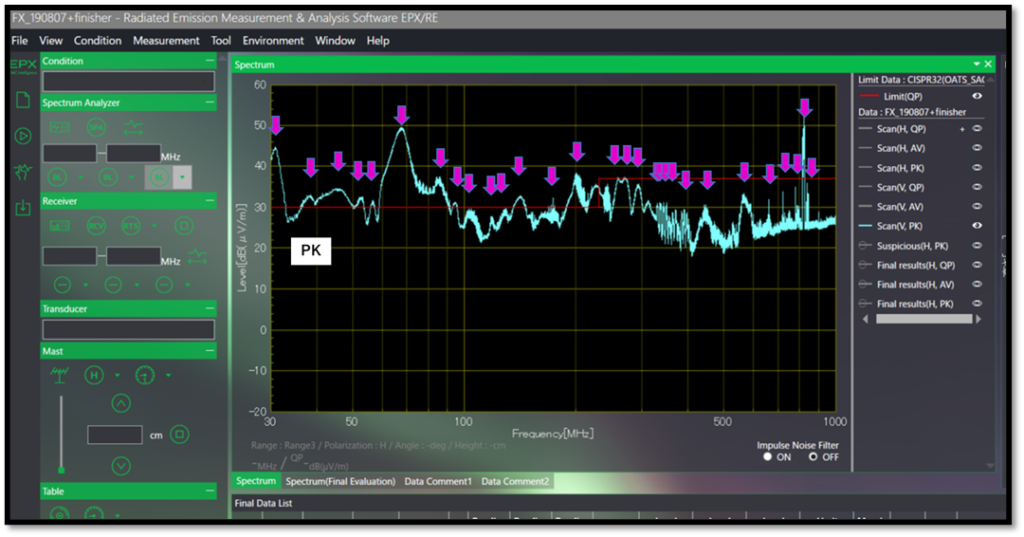
Same EUT is measured in conventional sweep measurement and RTSC measurement, and noise candidates for final testing are picked up by both.
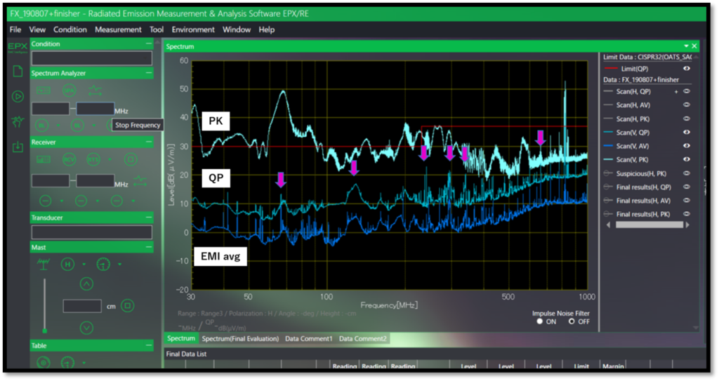
In RTSC, noise candidates are substantially narrowed down.
Example 2: “Reducing variation in measured values”
Values vary in each measurement, and the same EUT can produce different values than were measured before. The EUT’s operating condition needs to be confirmed, and at the same time, the accuracy of the measurements needs to be investigated. To begin with, with things like time-varying noise, if measurement condition settings are made without taking into account the timing of occurrence, noise will be missed, and the levels may not be correctly measured. With conventional sweep measurement, noise’s behavior had to be surmised and dealt with based on the user’s knowledge and experience. However, ensuring that each user carried out work of the same quality was a massive hurdle, and people often expressed concerns that results differed depending on the test engineer doing the measurement.
If RTSC is performed with the A-TDS’s maximum 350 MHz band, the true behavior of the noise can be ascertained via a gapless measurement. As a result, relative to conventional sweep measurement or narrow-band TDS, the variation of measured values is dramatically reduced, preventing labor from being wasted on doing things such as reworking and retaking measurements.
Below is a graph showing the variation (deviation) in each of three measurement methods: sweeping, narrow band TDS (around 30 MHz), and RTSC (a 30 MHz-100 MHz band is done at once). One can see how RTSC has relatively little deviation compared to sweeping and narrow band TDS.

Small Difference in Measurements (Peak Detection)
Note: Sweep measurement appears to have the least deviation for a portion of frequencies, but this is because impulse noise is missed, causing a “no noise” result. RTSC does not miss any noise and has little deviation in all regions.
Example 3: “Don’t be fooled by complex noise!” Narrow band noise buried within broadband noise.
Narrow band noise buried within broadband noise is a typical cause of difficulty for EMI measurement. Broadband noise can be found with things like switching power supplies, but recently, an increase in switching frequency has resulted in a tendency for a wider range of noise.
Conventionally, when sweep measurement was used, peak values and Max Hold traces are looked at in pre-scanning, but if the worst value is determined using the Max Hold trace, narrow band noise with a low level will be hidden in the Max Hold trace and will not be picked up as a candidate. However, in reality, most of the broadband noise is impulse-like and will not show up as large QP values. In contrast, the buried narrow band noise is continuous and can occur at a high frequency, large levels are shown in QP measurement. One must pay careful attention, as failing to notice this will result in missing noise that should be measured in final testing.
RTSC increases measurement reliability, as anyone can easily recognize this kind of narrow band noise buried within broadband noise and avoid the danger of missing noise that should be measured.
3. Products Supporting A-TDS
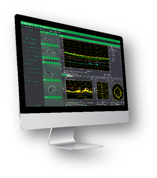 |
TOYO Corporation EPX series radiated and conducted emissions measurement and evaluation software This next-generation automatic measurement software can make full use of Accelerated TDS (A-TDS) and Real Time Scan (RTSC).
This software is the key to building and controlling a measurement system that integrates Keysight’s N9048B PXE receiver, equipped with A-TDS/RTSC functionality.
|
 |
Keysight Technologies N9048B PXE Full Compliance EMI Receiver An industry first, this full compliance EMI receiver is equipped with Accelerated TDS (A-TDS) and Real Time Scan (RTSC).
In addition to A-TDS and RTSC, this receiver is equipped with Standard TDS (narrow band TDS compliant with CISPR standards) and conventional sweep measurement, making it a full compliance receiver.
|
4. Additional Frequently Asked Questions
Q1. Is it possible to see a measurement demonstration on a real machine?
A1. Yes, there are demonstrations of the “PXE” by itself or combined with the “EPX Series” software. Demonstrations using a customer’s DUT in their anechoic chamber are also available. If interested, please contact Nick Sugawara or send an email to info@toyotechus.com.
Q2. Is the “PXE” a full compliance receiver that complies with CISPR standards?
A2. Yes, the “PXE” is a receiver in full compliance with CISPR 16-1-1:2019 and MIL-STD-461G.
In addition to being capable of conventional receiver scan measurement, the “PXE” can perform measurements in two TDS modes: Standard TDS (narrow band TDS) and A-TDS (broadband TDS). Of these, Standard TDS and receiver scan measurement fully comply with CISPR 16-1-1:2019 and MIL-STD-461G. Excluding some particular noise, A-TDS also complies with CISPR 16-1-1:2019.
Q3. When running QP measurements with Real Time Scan on the “PXE”, if dwell time (the time taken for measurement at a single point) is at or below the 1 second time constant, will I still be able get results consistent with those obtained using conventional sweep measurement?
A3. Yes. In RTSC, if the dwell time for QP measurement is set to 1 second or less, the resulting values will be consistent with QP values obtained using conventional sweep measurement and with a dwell time of 1 second or more.
Q4. For compliance measurements with the “PXE” and “EPX” systems, is it possible to follow the same test procedure as in conventional sweep measurement?
A4. Yes, aside from the new A-TDS (broadband TDS), as an EMI receiver, the “PXE” is capable of conventional sweep measurement, and you can also choose sweep measurement in “EPX”, allowing you to perform measurements as performed previously. In addition, in both Standard TDS (narrow band TDS) and A-TDS (broadband TDS), as is the case in conventional TDS, the TDS bandwidth can be switched step-by-step to measure a particular frequency span, similar to sweeping.
Q5. As a measurement equipment, what is the basic performance level of the “PXE” such as noise floor?
A5. The “PXE” has Keysight’s top-of-the-line spectrum analyzer, the “PXA”, at its base. At 1 GHz, DANL (display average noise level) can achieve -174 dBm/Hz, and even its basic performance outside of TDS is at the industry’s highest level.
Q6. Is the “PXE” capable of Click (discontinuous interference detection) measurement?
A6. Yes. Click measurement can be performed simultaneously on up to five channels (available as an option).
Q7. Can the “PXE” perform APD (Amplitude Probability Distribution)?
A7. Yes, it comes standard with APD.